Intro to shaders - Part 1
This article gives a quick insight into shader programming.
This article explains what shaders do and how to write them. It uses Godot 2.1 since that engine has the simplest shading language of all HLSL- / GLSL-like languages.
If you want to test the code you can download the project files.
A tale of two shaders
When we are talking about 'shaders' we are actually talking about two types of shader programs: vertex shaders and pixel or fragment shaders.
The task of these programs is to calculate the color of the screen pixels from the data stored inside a mesh, the assigned textures and other values like the camera position.
This requires two steps:
- Calculating the screen position of every vertex in the mesh
- Calculating the pixel color of every pixel inside every triangle that ended up on screen

Fragment shader
Let's start by writing the most basic fragment shader.
Setup
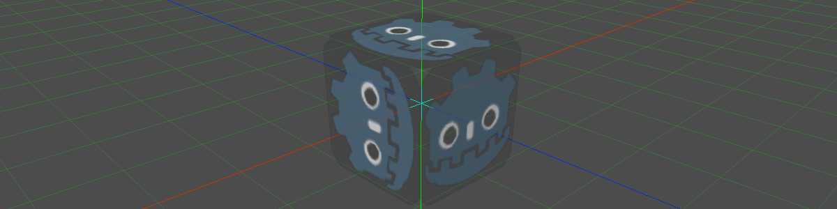
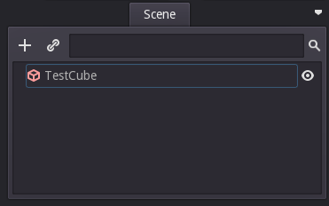
Create a new scene and add a TestCube.
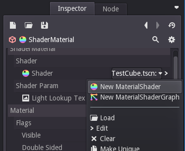
In the inspector create a new ShaderMaterial in the MaterialOverride property.
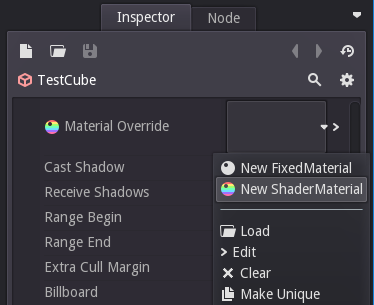
Edit the new ShaderMaterial and create a new MaterialShader.
writing the fragment shader
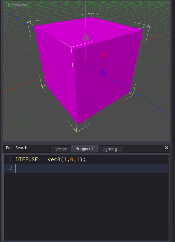
As I said the task of the fragment shader is to determine the color of one pixel. As a first test let's write a function that sets the pixel color to magenta no matter what. This is done by setting the value DIFFUSE to the color value of magenta.
Now since graphics cards are basically calculators on steroids they tend to refer to things in a very mathematical way. So in this case we pass the color as a three-dimensional vector, which is basically just another way of saying 'something with three values in it'.
In Godot's shading language we could have written 'color(1,0,1,1)' instead (the fourth value is for alpha), but in this
case we don't want an alpha component, and I want the code to be more similar to other shading languages, so I decided that we use vec3.

Vertex shaders
Let's switch to the Vertex tab now and try a basic vertex shader.
The most basic vertex shader will look slightly more complicated than the most basic fragment shader, simply for the fact that we can't completely ignore the inputs in a vertex shader. We were able to say 'No matter where the pixel is I want it to be magenta.' but we can't say 'No matter where the vertex is in the mesh I want it to have the same screen position.' because then the whole mesh would end up in one point and there would be no pixels inside it, so we couldn't see anything on screen.
So instead let's write a vertex shader that just does what the engine does for us if we don't write any vertex shader at all, i.e. place each vertex at it's intended screen position.
In order to do that we need to calculate the screen position and write it into VERTEX. (Actually in Godot we need to provide the position relative to the camera, but in most shader languages it's the screen position.)
We get that position by multiplying the incoming position SRC_VERTEX with a factor that the engine provides for us ('MODELVIEW_MATRIX').
Don't worry if you don't understand where that MODELVIEW_MATRIX is coming from - matrix calculations aren't that difficult, but for the most part you just need to know that a matrix is the factor between "spaces". If you have a coordinate in 'model space', i.e. in coordinates relative to the model's pivot point and you want to convert them to coordinates in 'camera space', i.e. relative to the camera position, you need to multiply with the correct matrix, in this case the MODELVIEW_MATRIX, which converts from model to view space.

Vertex shader effects
That worked, but it didn't really do something new, so let's modify the code.
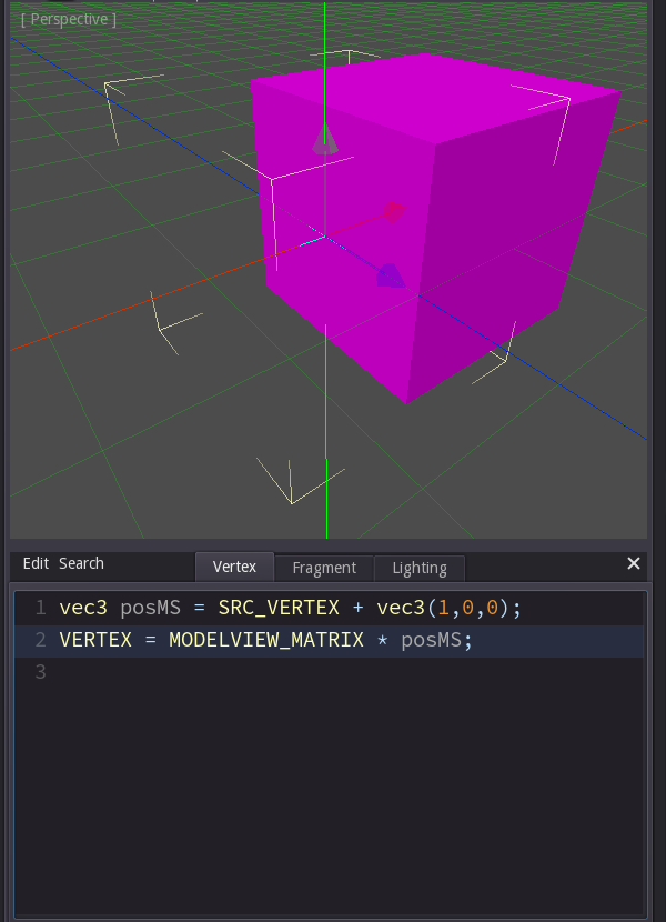
Let's add a little offset to every incoming position and calculate the outgoing vertex from that.
In order to do that we add 'vec3(1,0,0)' to the incoming vertex SRC_VERTEX and save it in a temporary vector called 'posMS' (for 'position in Model Space').
Then we replace SRC_VERTEX in the original line with posMS.
The result is that the cube is now drawn with an offset. Now this may not be the most exciting effect, but it shows one important thing: Whatever you do in the shader does not affect the game data stored in the engine. Although the cube appears at a different position the engine still thinks that it's at its original position (as you can tell from the selection markers). This is important, since shaders won't affect collisions, object selection with the mouse or culling.
Culling means that the engine will not bother sending objects to the graphics card that it thinks are not on screen anyway. So if you try to display an object at a completely different location it may not appear at all because it was culled by the engine.
Pixel shader effects
Let's go back to the pixel shader. Remove all code from the vertex tab and click on the fragment tab.
Now add 'uniform texture diffuse;' as the first line. This tells the engine that you want the fragment shader to have a parameter called diffuse that is a texture. This is done with the uniform keyword since this parameter is the same (or 'uniform') everytime we run that fragment shader.
Let's read a color value from that texture. To do that we need to use the 'tex'-command and tell it where to read and from which texture. Now we could calculate the position to read form the texture in any way we like - we could use the world position of the object, we could use the screen position of the pixel, but the default solution is to read the uv-coordinates from the mesh that were stored by the artist exactly for that purpose. We can access those simply by using UV in the code.
So we can get the texture color with 'tex(diffuse, UV)'. That would give us four values (red, green, blue and alpha). But in this case we only want to write color values (we'll check out transparency next), so we'll say that we want three values: the red value first, then the green value and the blue value last. We do that by appending '.rgb' to the line.
Filling the parameter
If you just copied the code your results won't look the same. That's because you haven't chosen which texture to use in the diffuse-parameter. Click on the back-button at the top of the inspector to go back to the properties of the material. There you'll find the new parameter and be able to select a texture.


Scaling the texture
Now let's write some code that modifies which part of the texture we are reading from.
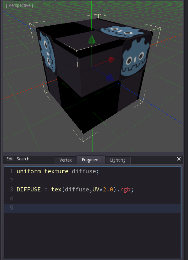
We can scale the texture simply by multiplying the coordinate to read from. For example if we multiply UV by 2 it will appear half as large, since it takes only half a UV-coordinate until we are reading the end of the texture.
Texture parameters
Now the texture is scaled, but half of the object looks a little weird. That's because we didn't tell the engine yet what it is supposed to do when we ask for coordinates that are outside the 0-1 range (= outside the texture), and by default the engine will just clamp the values, so anything larger than 1 is read as 1 and anything below 0 is read as 0.
In order to change that go back to the shader parameters in the inspector and edit the texture parameter. There activate the check box 'Repeat' to have coordinates use the fractional part only, so 1.5 turns into 0.5, 17.2 turns into 0.2 etc..


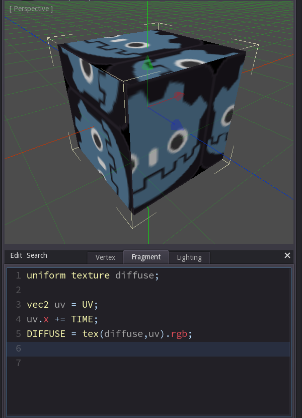
UV-Animation
Now let's add an offset to the texture instead of scaling it, and to make it more interesting let's make the offset time dependent. The input TIME gives us a value that constantly counts up, 1 per second. This time I used '+=' to increase one value, so uv is the original UV coordinate, but its x value is increased by the TIME value. That means that there is an offset in the direction of x that grows constantly.
Other ways to achieve the same result would have been to write
vec2 uv = UV + vec2(TIME, 0);
or
vec2 uv = UV + TIME * vec2(1,0);
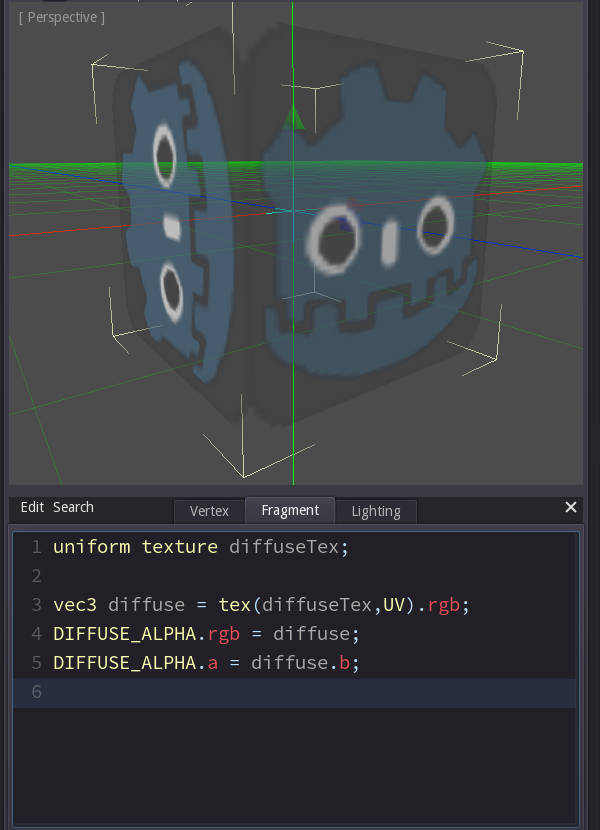
Transparency
So far we have written the colors into DIFFUSE. If we want the object to show transparency we need to use DIFFUSE_ALPHA instead.
In this example we read the color from the texture as we did before, but now we write the color value into DIFFUSE_ALPHA.rgb and then set the alpha value DIFFUSE_ALPHA.a to the value of the blue channel of the texture color.
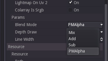
Blend mode alpha
Again calculating the correct values isn't quite enough, we also need to tell the material to use the alpha value for blending by setting the Blend Mode to PMAlpha.
Lighting shader
So what about the lighting tab? Didn't I say that there were only two kinds of shaders?
That is true from the graphics card's perspective, but several engines have introduced the concept of lighting or surface shaders. The idea is that the fragment shader that calculates the color of a pixel should be split up, since the resulting color depends on two groups of factors:
- Properties of the model (like its geometry, the textures etc.)
- Properties of the environment (like the color, position and brightness of the lights)
That's why there are two tabs: the fragment tab does not actually contain a complete fragment shader, just the part that isn't about the light. The lighting tab contains the second half of the fragment shader and deals with all the environment factors (i.e. mainly the light).
Let's again first rewrite the most basic shader to see how it works.
We need to calculate the color of the light that is reflected from the current pixel, so LIGHT needs to be set to a 3-dimensional vector (for red, green and blue of the light).
This color depends on the color of the surface and the angle of the incoming light. (We are going to ignore other factors like the light color or the light strength for now and just assume that they are white resp. 1)
The easiest formula to calculate the brightness of a light from the angle between the light and the surface is the dot product. Again the math isn't that hard, but it's ok to just accept that the dot product calculates exactly what I just described.
This kind of lighting is called "n-dot-l-lighting", since the brightness is calculated with the dot product between the light direction and the normal of the surface. If the light is shining parallel to the normal (i.e. directly at the surface) the dot product is 1. If it shines parallel to the surface the dot product is 0. And when the angle is even larger it's below 0, which happens on the side of the object that points away from the light source.
When it comes to light the graphics card doesn't care about values below 0 or above 1, it will always just clamp the values to this range. (Negative values become 0 and values above 1 become 1.) We just need to know that the resulting values range from -1 to 1 when we will use the dot product for custom shaders like in the next step.

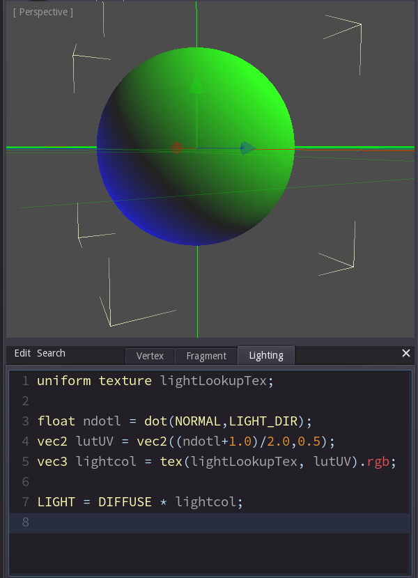
Lookup textures
Shader programming revolves around just a handfull of techniques. One of them are lookup textures. The idea is this: instead of calculating a value using a formula we use an input value as a coordinate and then read at that coordinate from a texture. That allows us to edit relations using applications like Photoshop.
Let's look at an example:
In the first line we declare a new texture parameter. Again it needs to be filled in the inspector. In this case the texture is just one pixel high and contains a gradient from blue over black towards yellow.
The idea is that we calculate the ndotl-lighting as before, but instead of directly using the result as a factor we use it as a coordinate to read a value from the texture. Thus the highest brightness (1) becomes the coordinate (1,0) where the texture is yellow. Complete darkness becomes the coordinate (0,0) where the texture is blue.
Line 3 calculates the ndotl-value.
Line 4 creates the UV coordinate from the ndotl-value. You may be surprised by the values in that formula - here's why it looks like that:
- We don't use 0 as the y-value because it's not a good idea to read the color directly from the edge of the texture. By using 0.5 we are reading from the middle of it.
- We don't use just ndotl as the x-value because the ndotl-value ranges from -1 to 1 but the texture coordinates range from 0 to 1, so instead we add 1 (so the range changes from (-1->1) to (0->2)) and then divide by two (so it becomes (0->1)).
Finally we read the texture color in line 5 and multiply it by the object color in line 7.